As I’ve mentioned previously on this website, I’ve been organizing a minimal home recording studio for Lee Safar for the album I am currently producing for her. In order to save money and also get the best possible sound we can, I’ve decided to DIY a lot of the recording equipment.
Jeff Steiger, owner of the ClassicAPI company was amazingly friendly with all of the questions I had for him when deciding to purchase this kit. After putting in the order, about a week later, the box arrived:

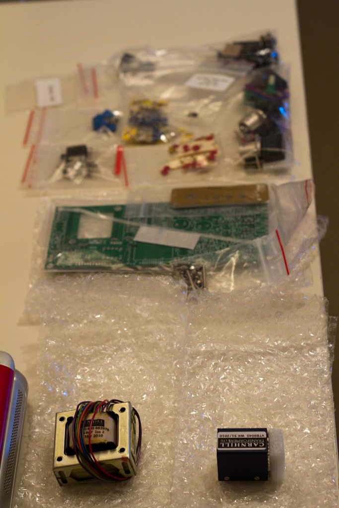
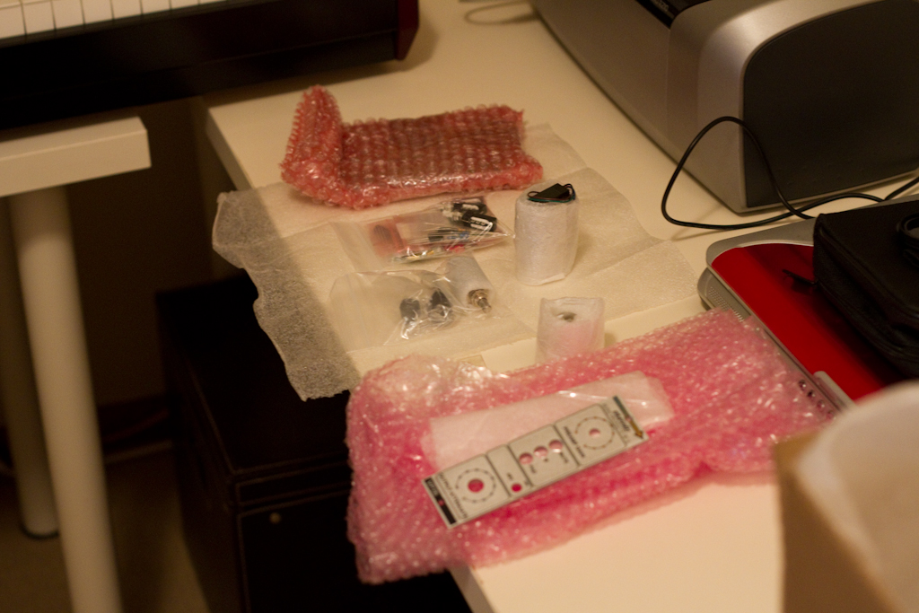
Everything was beautifully packed, and the initial reaction was “wow, this is one seriously professional piece of kit….”.
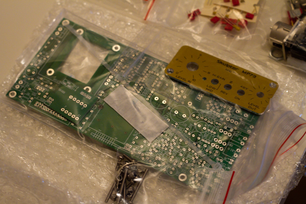
Here you can see the silk-screened front panel ( which was shipped in the wrapping it’s sitting on ):

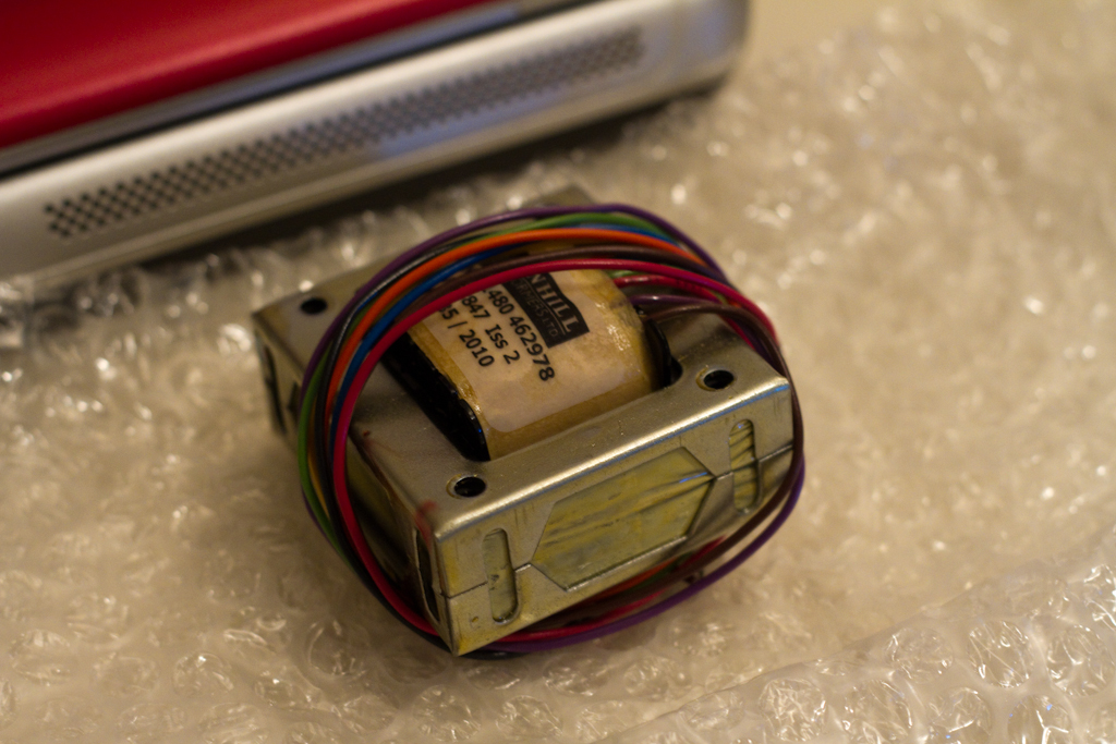
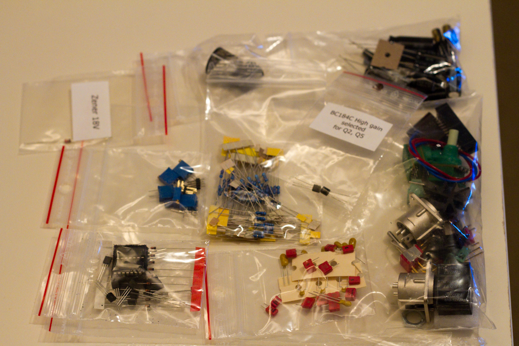
Here is a glimpse of the input transformer, output attenuator and input gain control and associated mounting hardware:

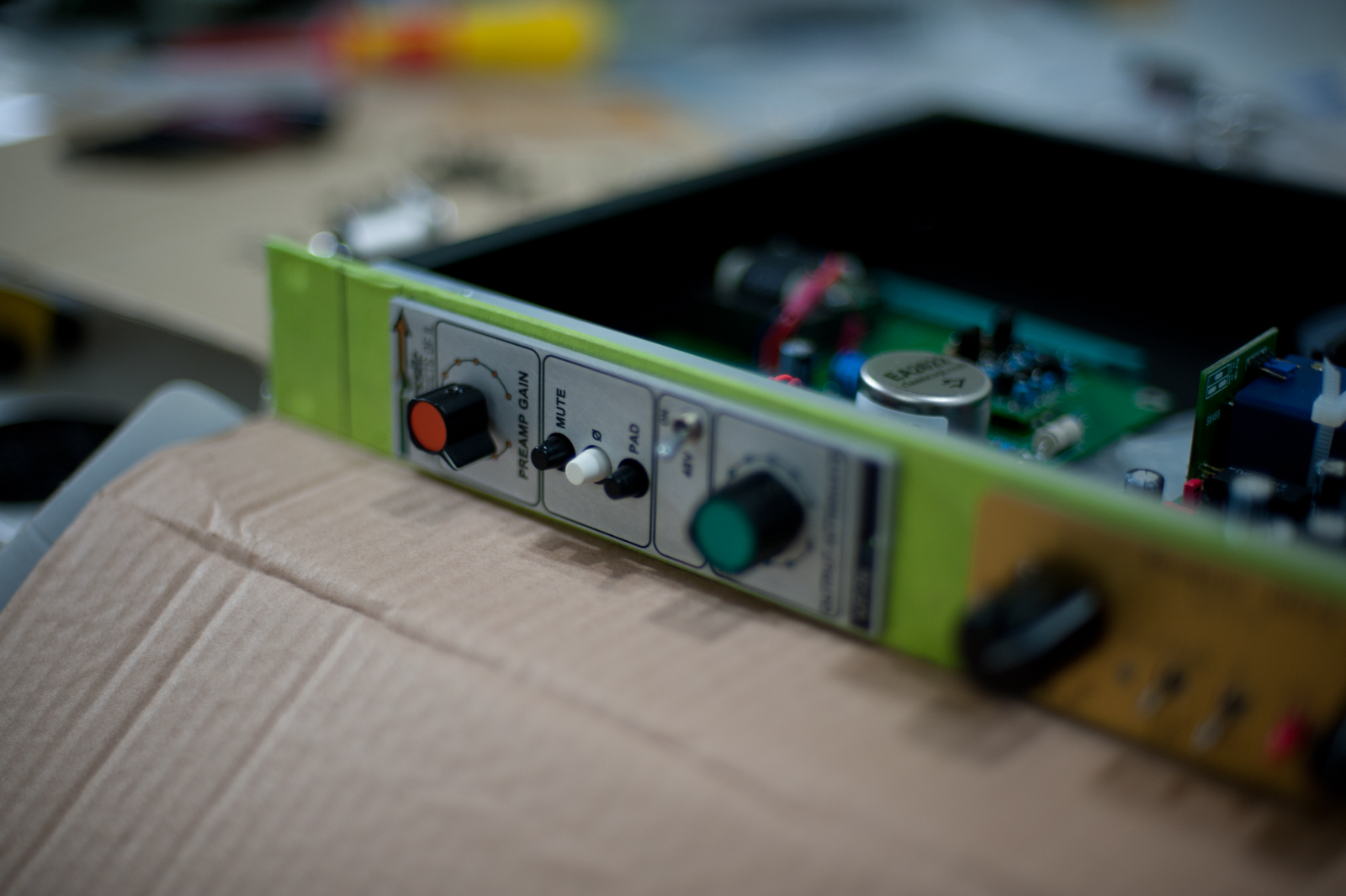
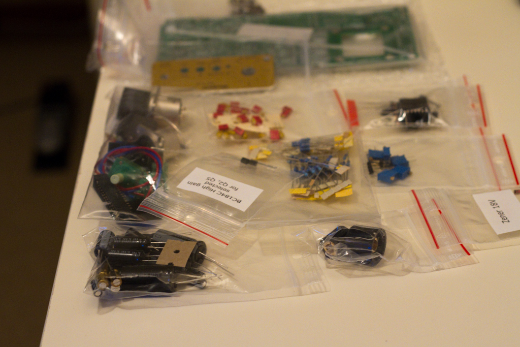
These are the main front panel switches for Mute, Phase reverse and Pad:

Here is the wrapping for the main mounting frame:

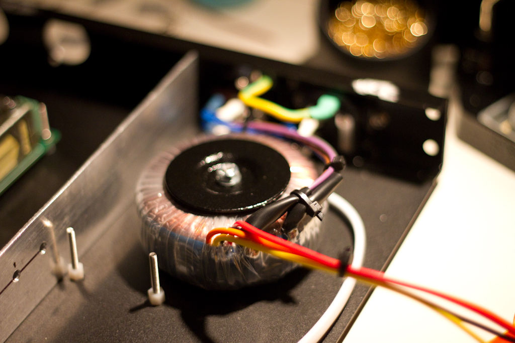
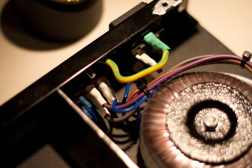
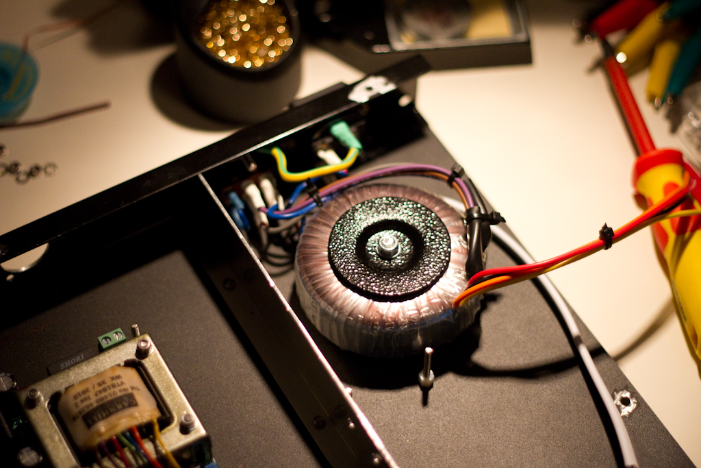
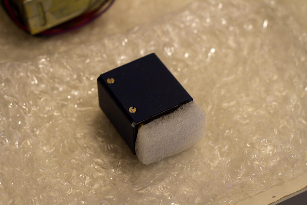
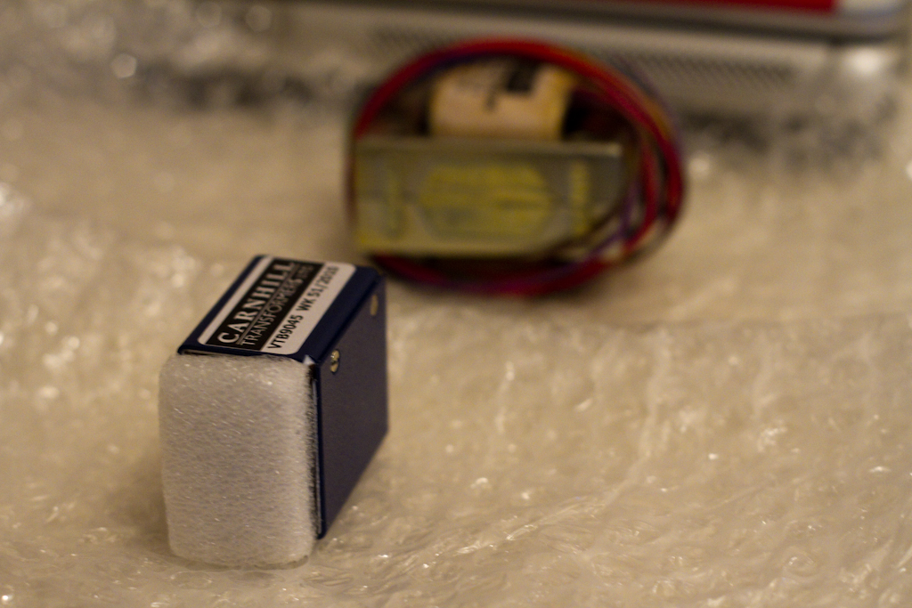
The gorgeous input transformer:

A close up of the switches including the 48V Phantom power switch:

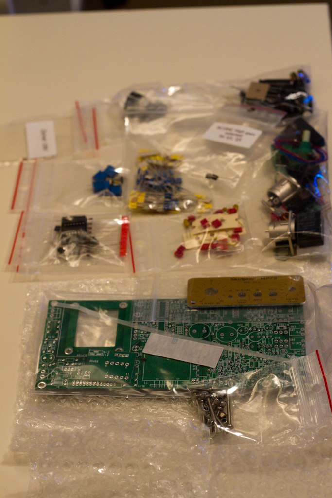
Here is the top and bottom of the PCB that comes with the kit:


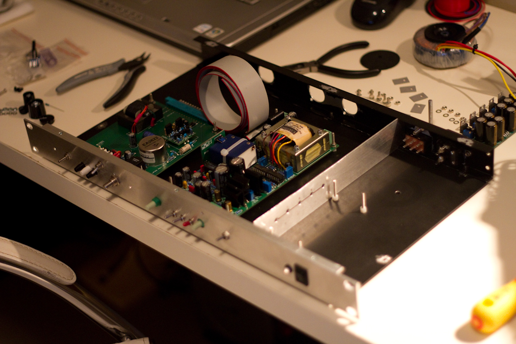
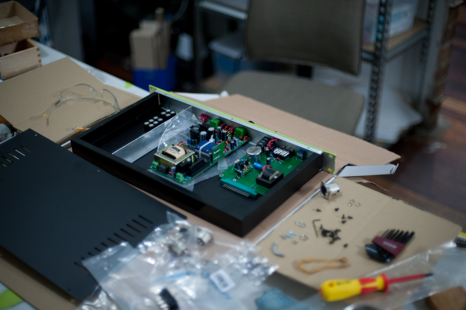
Here is the whole lot on the table:

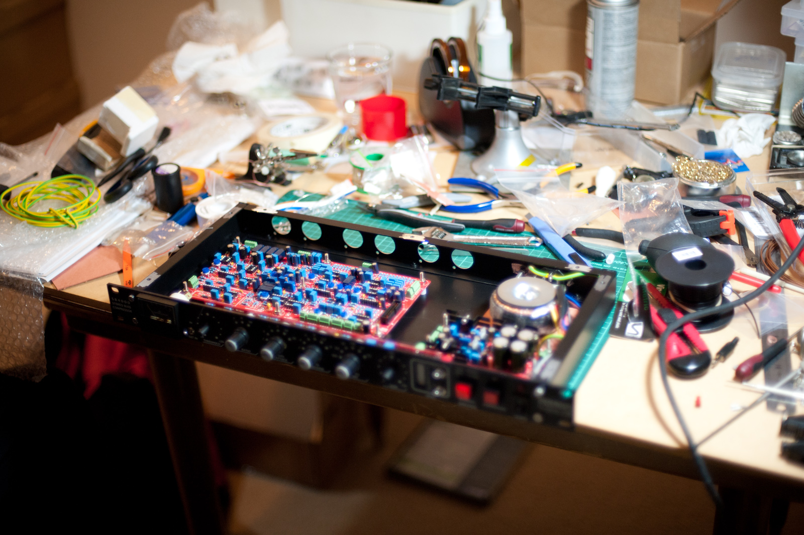
The first thing I did was set up the workspace ( yes, I am using a Country Road magazine as a work mat – that’s how I roll – I’m not quite as well setup as when I was working at talsit‘s house! ):

Then I put in the resistors:


Followed by the diodes:

Then the latching push switches:

Then the blue Murata ceramic capacitors:

Then the large capacitors, radial and standard electrolytic went in. The Mill-Max sockets also went in at this stage. You’ll notice the botch job of the large 470uF capacitor with it’s horrible soldering. A note to those building this kit – use flux! I didn’t and it made soldering to the ground pads exceptionally difficult due to the massive thermal inertia of the exceptionally thick PCB. I bought some flux the next day and used it to fix up that area ( which you will see in later photos ):

The input transformer went in next:

Then the output transformer ( also note the cleaner solder joint on the large axial 470uF capacitor that I cleaned up by application of flux and re-soldering ):

You can see the output attenuator now after being added:

Next the 48V Phantom power switch went in, and I started to assemble everything into the main frame, along with the front panel:


Next the knobs went on to the potentiometers:

And that was the end of the basic ClassicAPI VP26 build. A preamp isn’t much without an amplifier now is it? So the next part was building the gar2520 Discrete Operational Amplifier (DOA) – which performs the actual amplification task. It’s a compatible physical layout to the original API 2520 units ( which can also be used in this kit as DOA’s ).
The first part of the gar2520 build is the pins for insertion into the Mill-Max sockets of the main VP26 board:

Next go in some resistors and capacitors:

Then the diodes:

Next are the main transistors:

Now we add some more resistors and capacitors:

And more:

And more:

And more:

And more:

And more:

And then, finally, the last parts go in to finish off the gar2520 DOA:

Now the DOA can be inserted into the main board:


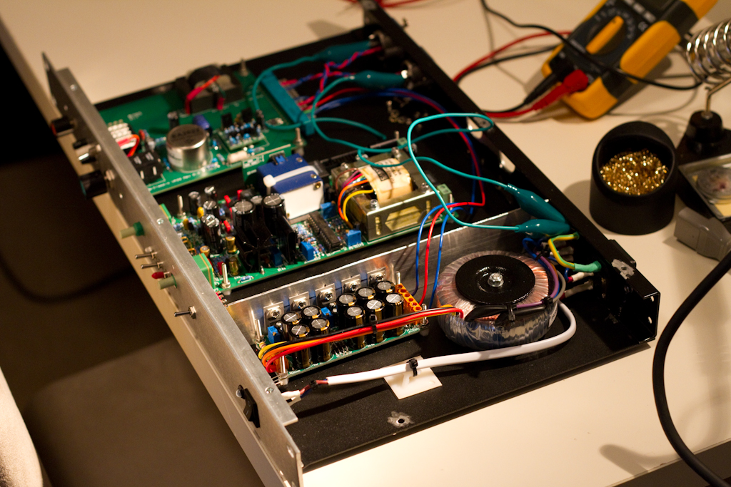
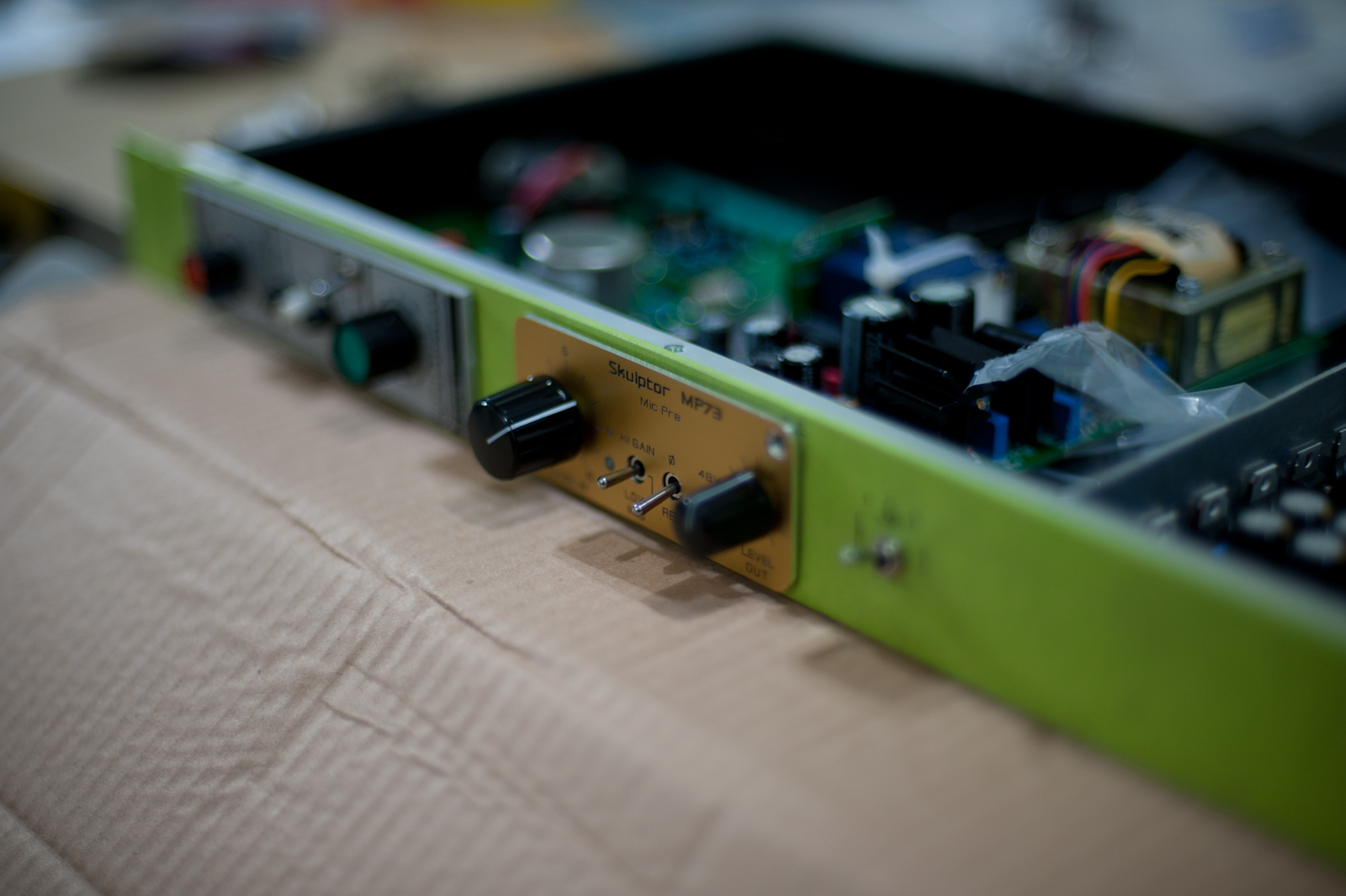
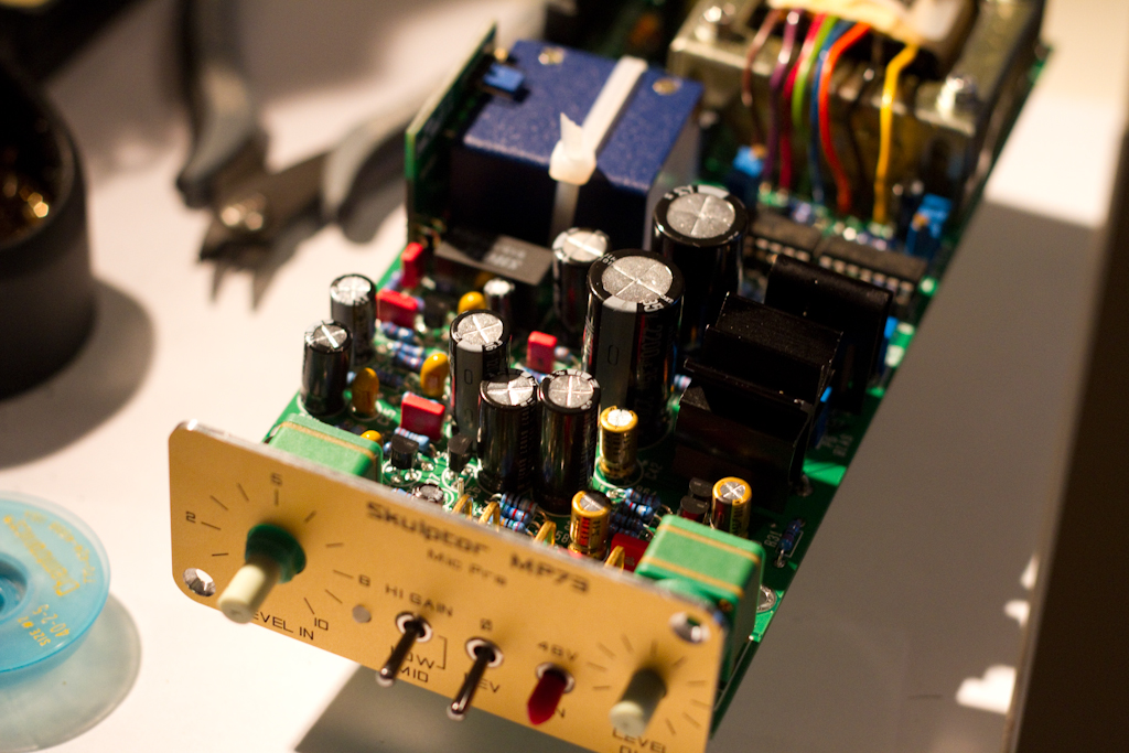
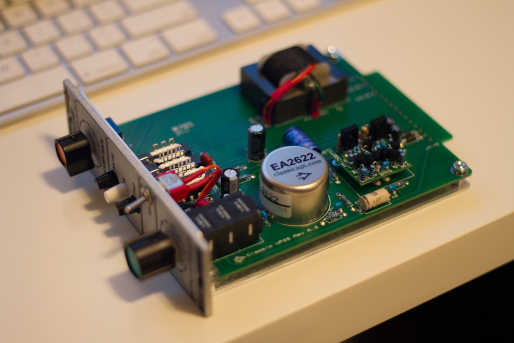
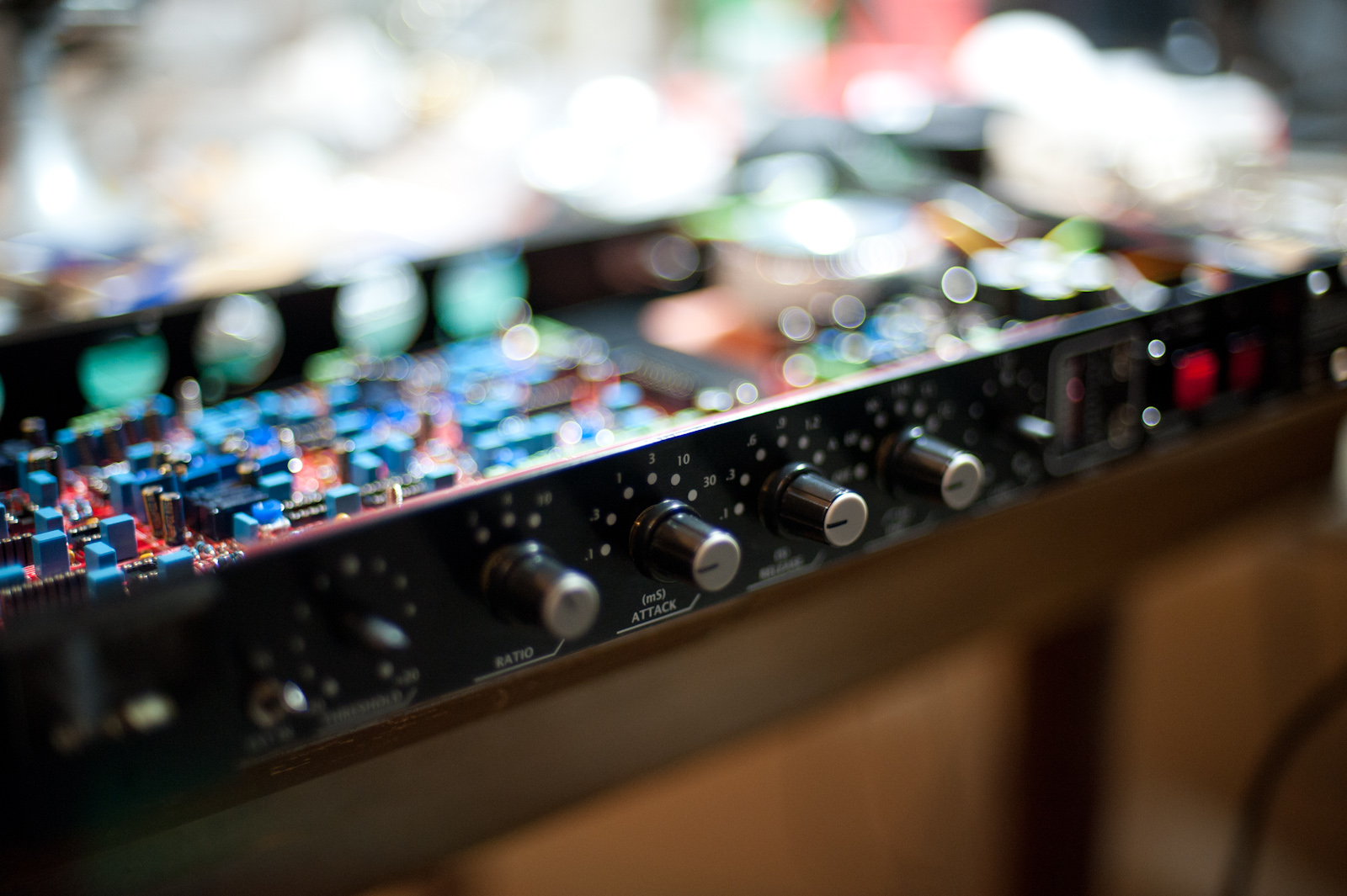
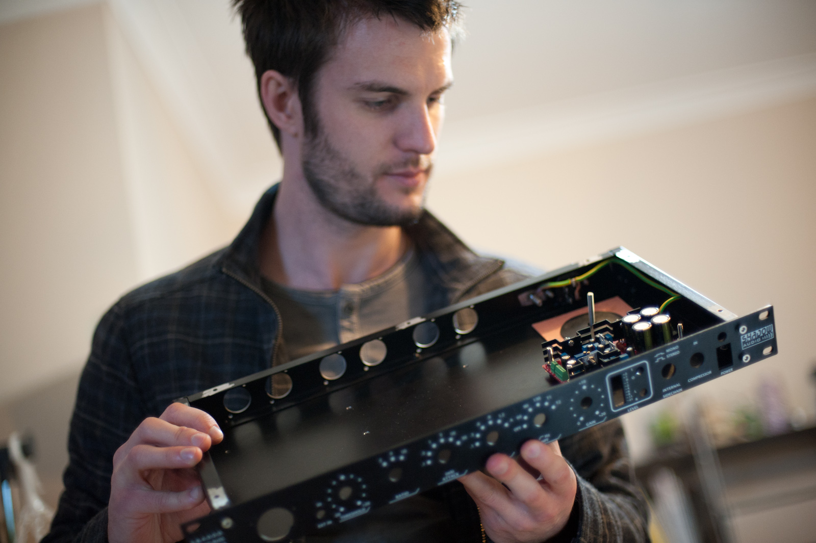
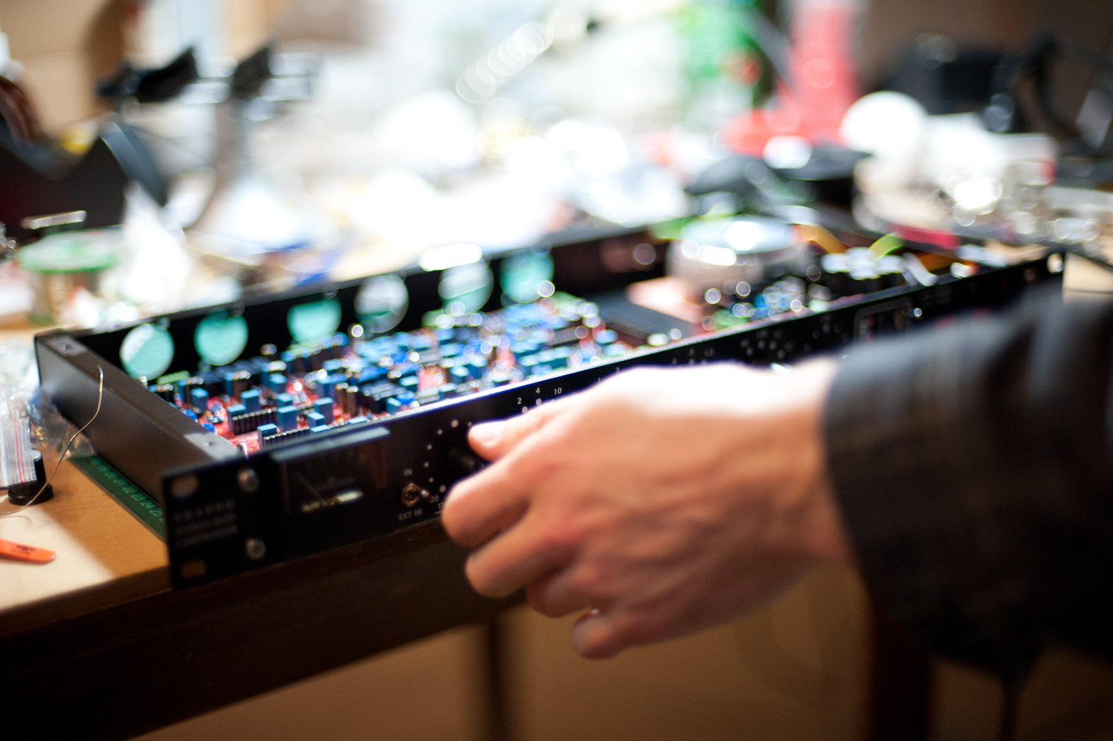
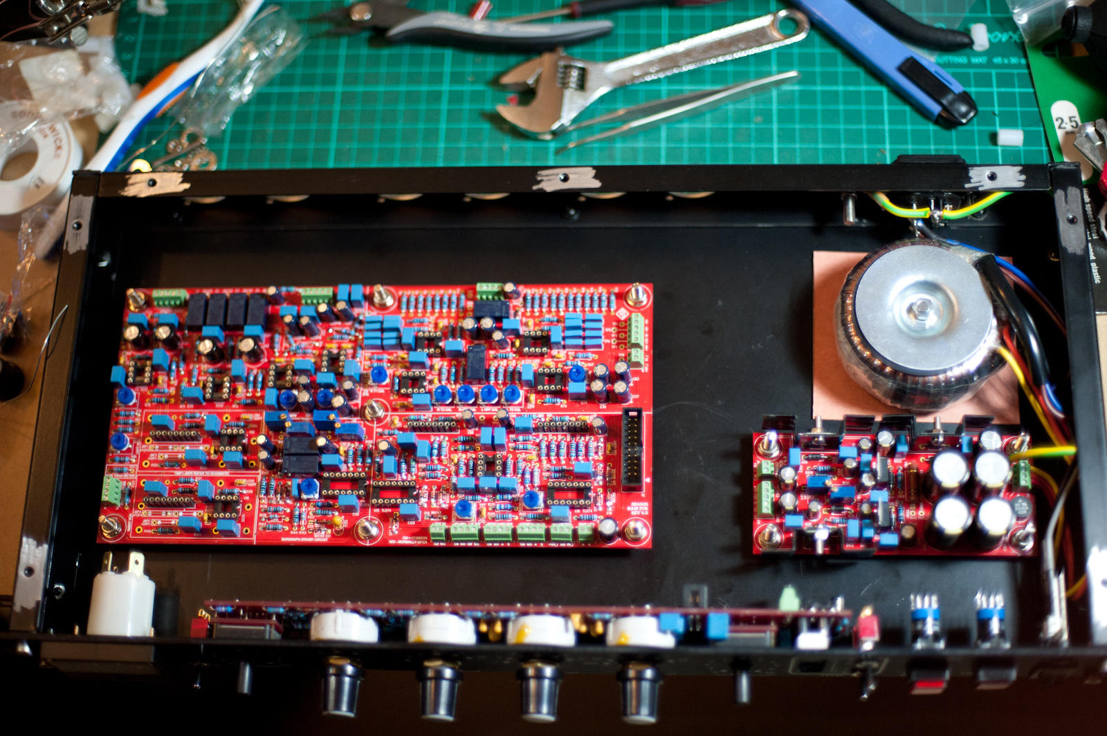
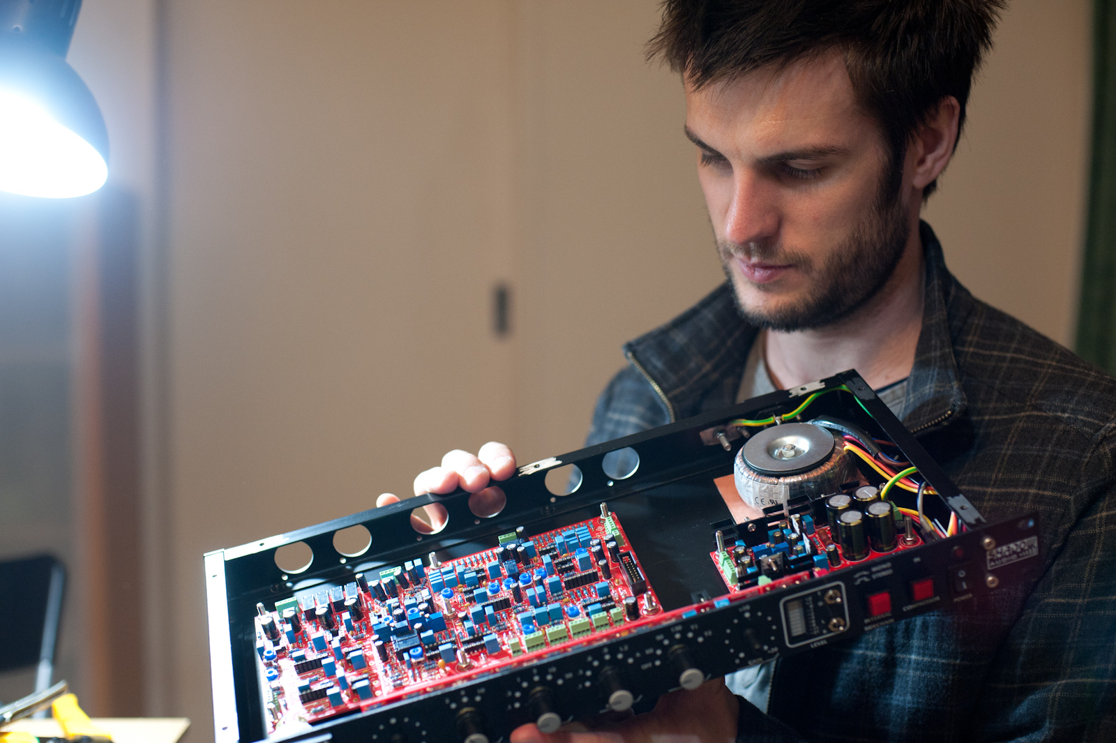
And now it’s time for some modelling shots of the finished ( but untested ) product….


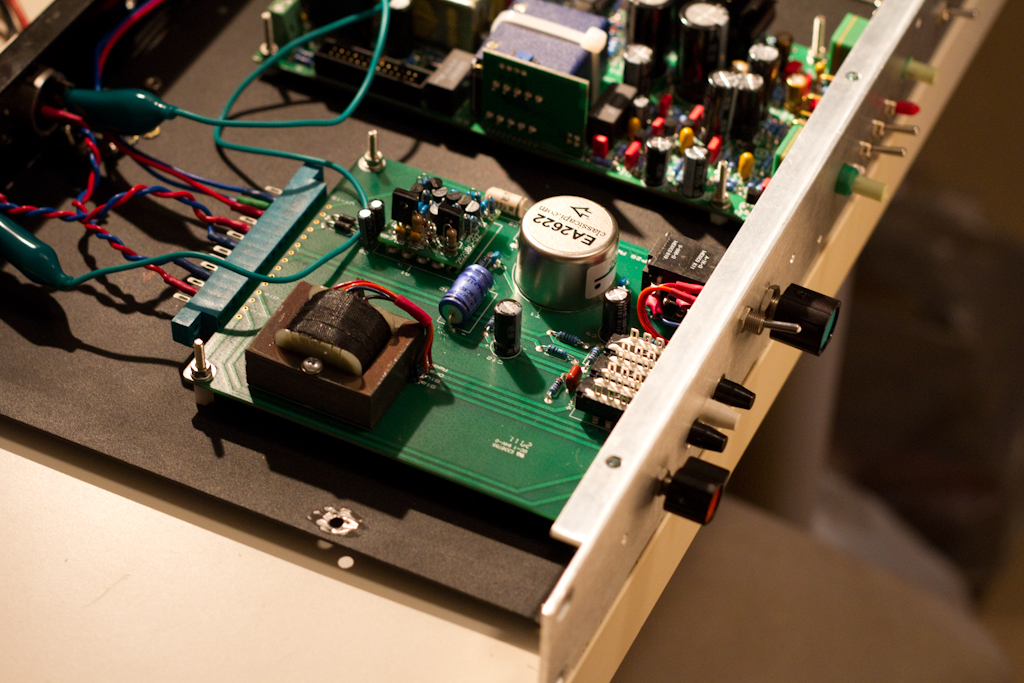
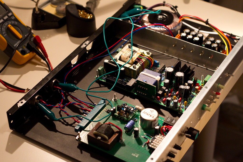
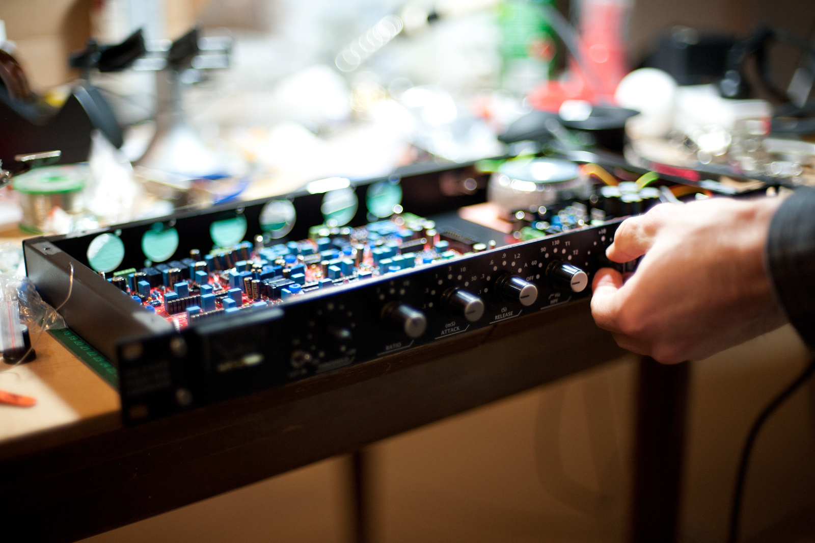
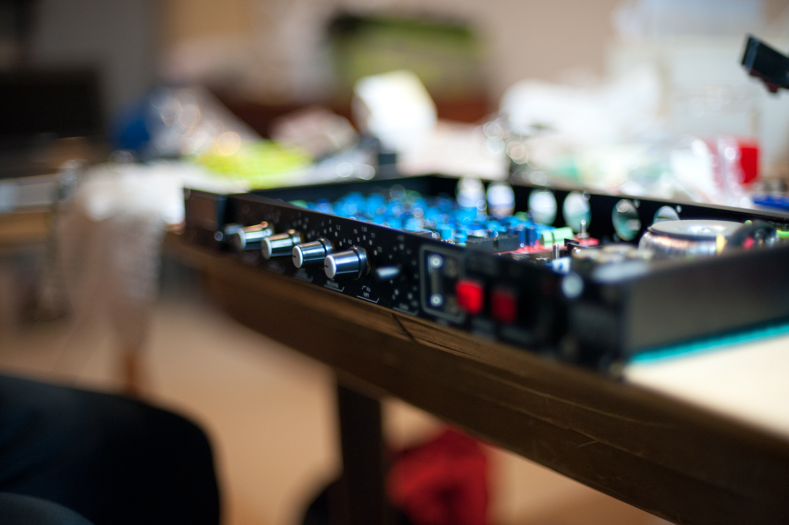
And now for some close-ups:


And there you have it. Next up, the Neve-style Sound Skulptor MP73 build. Stay-tuned for that, and the testing of this pre.


