After a rather long delay, it’s time for a BIG update!
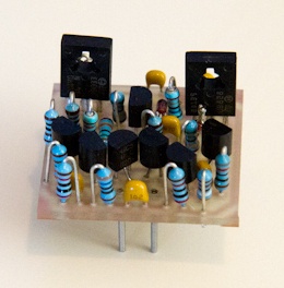
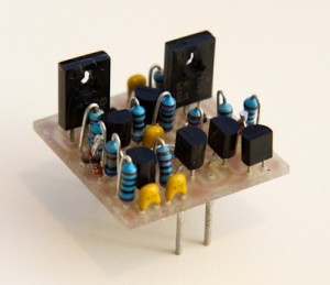
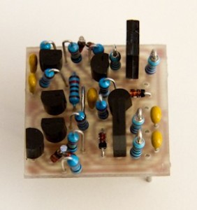
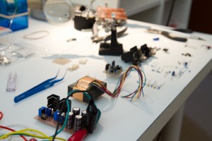
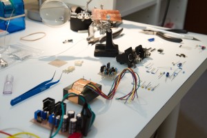
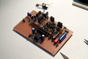
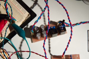
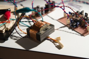
First of all, the 2520 did work, perfectly, and here is what it looked like after I soldered it together:
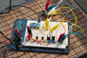
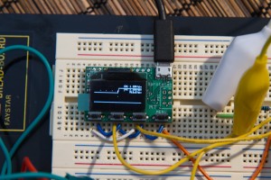
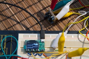
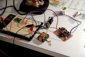
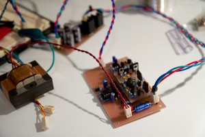
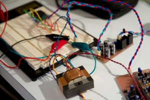
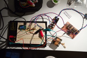
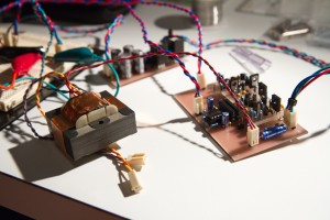
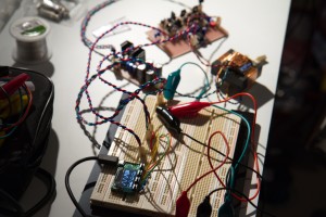
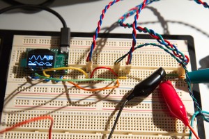
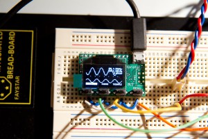
Next up I did some testing. Here I am using the Xprotolab miniature DSO for all of my testing (since it also incorporates an extremely useful function generator). The power supply was on the breadboard, and the DOA being tested is connected to its off-board components via alligator clips. I fed in a signal from the Xprotolab function generator using the 2520 amp in differential mode (from the compressor circuit), and got back the same signal that I put in – perfect!:
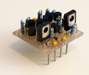
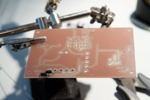
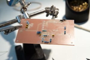
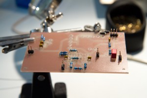
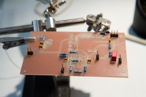
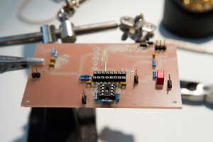
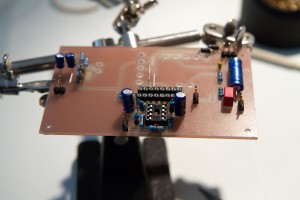
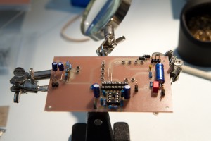
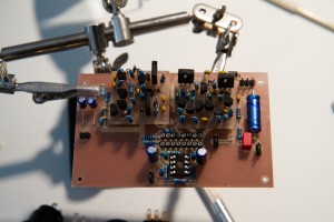
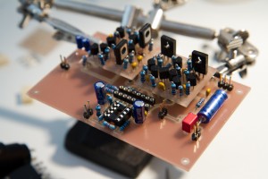
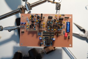
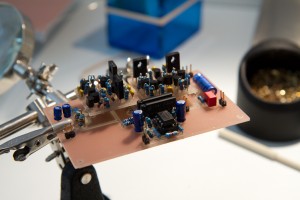
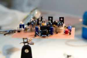
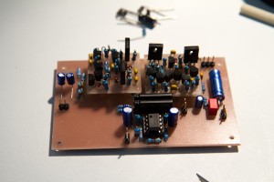
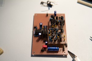
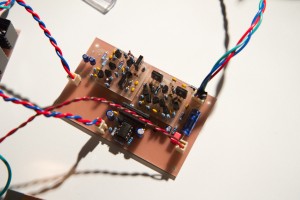
The next piece of design was the 2510 discrete operational input amplifier. This is basically a less beefy version of the amp above, with a much smaller DC offset, and less power handling capacity. However, always wanting to improve things, I have modified (IMO, even improved upon!) the original design, and added beefier output transistors in an attempt to improve the life of this generally gutless amp (the originals apparently blow-up quite frequently) and also added some form of output short-circuit protection, should the need ever arise that is has to be used. My layout, CNC, and subsequent physical build, looked like this:
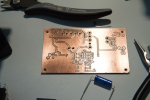
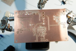
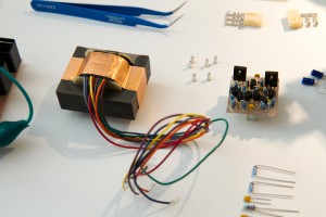
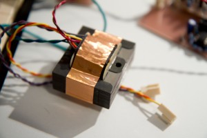
In order to keep things moving along, and save cost at the same time, I decided to split the rather complex compressor side-chain circuit from the audio path, and build the audio path of the compressor first. This resulted in a partly populated, but working audio circuit layout, where the 2510 sits in front of a pair of 2180LB THAT Corp voltage controlled amplifiers (VCA’s), which are in charge of the actual gain change due to compression, and then through the output 2520 to drive the ClassicAPI 2503 output transformer. This circuit is both simple, with not that many components in the audio path, and extremely high-performance, and also a better systems test for my amplifiers, so, this is what it looked like after this board was CNC’ed:
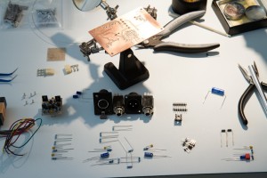
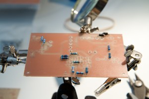
And here the audio path is being populated with parts:
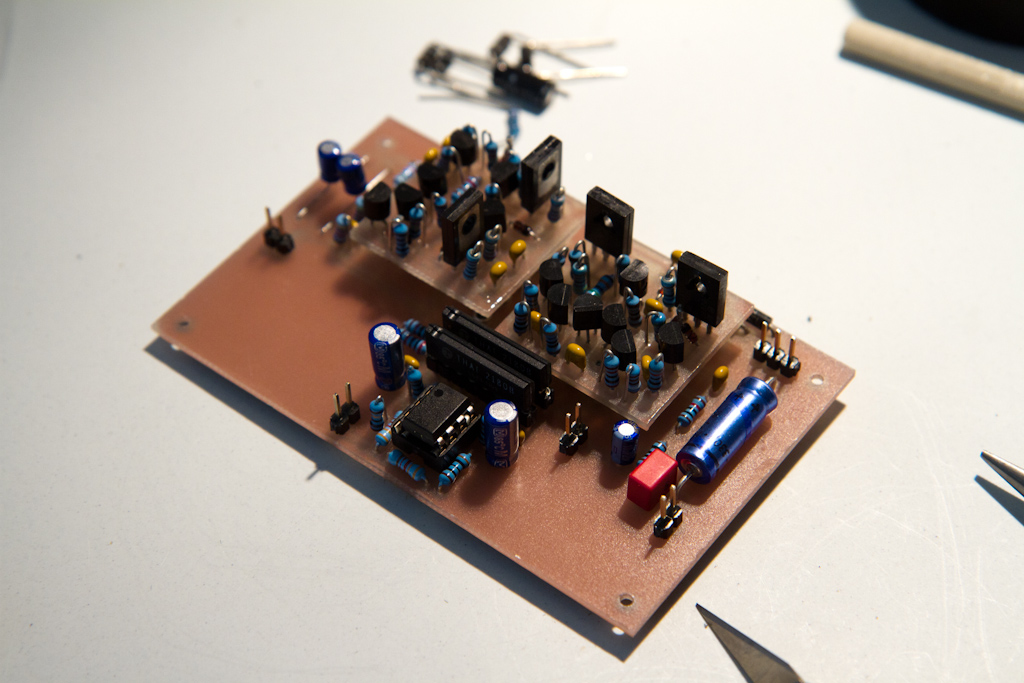
Next I fit the two DOAs to the audio path board, and then did a bunch of shots to show it off, cause I thought it looked pretty cool, and it was the most complex thing I’d ever designed at the time, so I was very proud of it!
Then it was the scary time were you have to test everything to make sure it all works! Luckily it all did, and passed the signal precisely as calculated on the simulator:
After successfully showing their operation, the next step was to get the DOAs manufactured by a professional PCB fabrication plant, which will be the next part of this compressor series.
