Hi everyone!
It’s been a while since my last post. I took a holiday and went to Italy for 5 weeks. It was completely awesome and gave me a lot of time to think about a lot of different things.
Whilst I was away a had quite a few crazy ideas, and this was one of them…. a custom compressor based somewhat on the API 225L:
My idea however is to take it further than the original, much much further. In fact it will probably more resemble the API 2500 when it’s finished:
I had to start somewhere – so I began by breaking down the problem, as I always do, into manageable chunks of work. The first was the famous API2520….
One of the key components of all of API’s gear is their Discrete Operational Amplifiers ( DOA’s they are called ).
In particular, the API 2520 ( image courtesy of http://www.silentarts.de/ ) DOA is extremely well known in audio circles and a key component in “the API sound”. So to begin designing this project I knew I had to start there. There are many commercial options out there for API 2520-style DOA’s, from kits, to full clones, or even buying directly from API themselves. After a lot of investigation I found the best option would likely be one I’d already used before – the gar2520 by Gary Barnett of Barnett Industries, which I discovered as an optional extra with Jeff Steiger’s ClassicAPI kits. In particular, I remembered it from one which I had already built; the VP26 microphone preamplifier.
After some more investigations I quickly realized that the 8-10 2520’s I would need to buy to both test and then finish the compressors ( I intend to build 4 of them ) was going to be too high. So I decided to do something a bit crazy and see how much it would cost me to find the original circuit on the internet, tweak it, source the parts myself, do a custom layout of the circuit board, and then try and build it…. At the very least I thought I could build some test devices, and then once the compressor design was finished I could replace them all with the gar2520’s ( because I know they are of such high quality ).
The cost difference for me was quite compellingly in favor of jumping in the deep-end and building them myself – so that’s precisely what I’ve started to do.
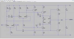
Firstly I built the circuit in LTSpice ( based on the “original” I found here http://www.waltzingbear.com/Schematics/API.html, along with various modifications and observations through many many hours of online research and forum snooping! ) and simulated it, tweaking the layout and component selection for parts I could source directly and quickly in Sydney, Australia, from element14 ( I think I only ended up having to change one resistor value since they didn’t stock it…. ) and ended up with the following:
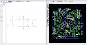
From there, I rebuilt the schematic in the free version of Eagle PCB, and came up with a PCB layout that was single-sided ( for ease of CNC-routing ) and matched the original API 2520 size and footprint:
From what I can tell, this might be the first single-sided PCB layout for a 2520-like circuit that doesn’t use links or off-board wires to complete any of the circuit paths…. If so, then I’m pretty proud of it!
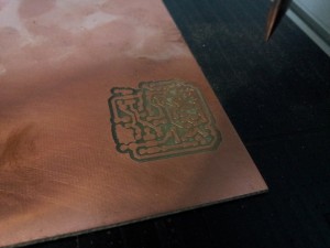
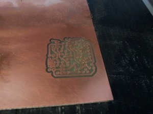
From there, I took these files ( after a good friend of mine, and PCB-making-expert – talsit – checked them for me ) to Robots and Dinosaurs ( a Sydney Hackerspace ). The CNC machine they have there is completely awesome. Even though this was the first time I’d ever used it ( I must have just gotten lucky…. ), after loading in the files, and asking Gav ( Robots and Dinosaurs supreme resident hacker! ) a lot of questions, I got straight to it, and the result seems pretty text-book….
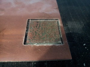
Here was the progress after the first layer, which eagle labels an “etching” layer:
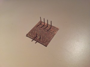
Secondly the holes get drilled:
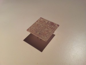
Then the board is “milled” out to become its own entity:
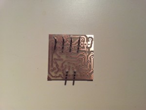
And here is the result – a rather nice little amplifier PCB ready to be populated:
More to come soon ( hopefully in a couple of days ), when I actually populate the board and do some tests to see if all of my pre-planning has actually worked….


Hey Luke, nice work on getting all that onto such a compact single sided PCB. Very pleased to see the skills of CNC PCB prototyping getting passed on to a wider group. Talsit and Gav are very smart guys, and a great resource.
Very cool! How’d this turn out?! I’ve been planning on doing my own layout for a home etched 2520 doa. Don’t understand why the ones based on kits stick to the smallest possible footprint ending up with the weird off board wiring. Yours looks great!
Hi Sasha!
Thanks for reading the blog!
This project is still in progress, and I have a few in parallel with it now too.
In particular I have an analog synthesizer that I am designing, a preamp/EQ and then the compressor – so lot’s to still do yet!
But I will definitely keep you posted.
Thanks again for reading! I’ll be sure to have a lot more happening early next year.
Dear eTheory,
I have been using the free version LTSpice & I wanted to know if you have used LT & if you find Eagle to work better. From the picture they look very similar, however LT does not have variable parts or continuos simulating (wording). I keep telling myself it is what I need & not what I want, however if you have any insight, I am open-ears:”)
-thee.
Also,
Your board looks amazing, I have-yet to etch any boards, still on the point-to-point & loving it, however I feel I am ready for an internal-upgrade;”)
Stay up & May the source be with you! : :
-thee.
Yo EVolutionary.THeory, where did you find the 225L schem?
If you got it on hand shoot me an email brother!:”)
-=-thanks boss! . ;2πø∞
-=thee.
hi
compliments 4 your work.
I would like to attempt at this discrete opamp. Should be nice if you can send me the schematics (the link http://www.waltzingbear.com/Schematics/API.html give only a distorted image) and great the eagle files.
thanks a lot
M
Hi Max,
Thank you for your interest.
I will be selling PCBs for these online soon.
I spent countless hours testing and designing these devices, taking pieces of information I found on the net and building/adjusting/prototyping/updating many times before getting the levels of performance they now have. It would be hard for me to justify giving away all of these hours of work and design for free, hence the plan to soon sell PCBs to try and recuperate some of my costs.
Regards,
etheory.