This is the second post along the road to DIY compressor bliss….
Picking up where I left off last time, I am starting by creating my own, super cheap, DIY version of the API 2520 Operational Amplifier. It will be used for the input and output stages of my take on an API 225L/2500 Frankenstein compressor. Initially I also planned on cloning the API 2510 used on original API compressor input stages, but my simulations have led me to believe that I will get better and more reliable performance from the same configuration, but using an API 2520 instead. All the basic resistors, capacitors and transistors arrived from element14 this week, whilst I was away for Christmas. They are ready to be soldered:
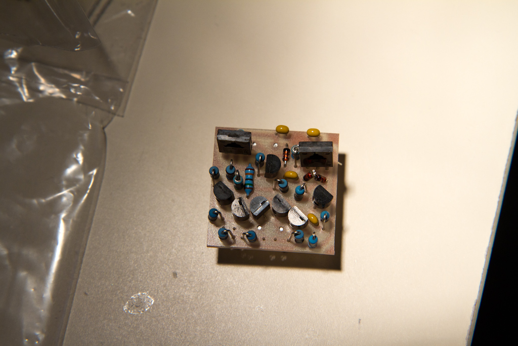
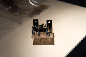
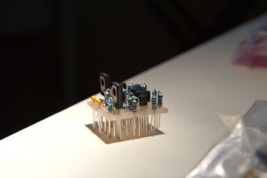
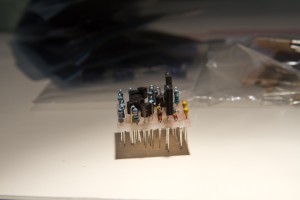
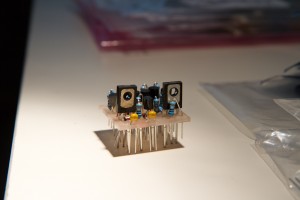
After inserting some bits on the PCB I made in my last post, here are the results of the layout – everything fits perfectly – all of the pre-planning paid off ( it’s just missing 2 capacitors, which had not arrived when these photos were taken ):
This view from the top really shows how nicely the placement is working:
Tonight I’ll be soldering the parts to the board to see how it all goes ( I’ve never worked with a DIY CNC’ed PCB before ), and if I get time, I might even run a quick test on it. More to come soon….


Hello,
I’m following with big interest your diy project of api compressor.
Thank you for the description of all the process.
I see that you begin with thé api 2510 discrete amp.
I’m searching some information about it. Specially thé schéma tics, do you have it ? And eventually is it possible for you to send to me?
Again
Hi Marchadier,
As per the article states, I didn’t actually start with the API2510, but the API2520, which is a more complex amplifier with a greater output current handling capacity – you can see on of many versions of the circuit diagram here: http://web.qx.net/jgreenlee/API/2520bc.JPG – which may or may not be correct (this isn’t the one that I used – the one I started with was extremely wrong, and I had to spend time fixing it).
Get yourself a copy of the free LTSpice circuit simulator, learn to use it, and play – you’ll be able to adapt it to suit your situation. There is no point me handing you a circuit diagram, since you’ll really need to customize it for your particular application.
I ALSO did manage to make a “similar-to-a” API2510 input stage, but, it’s not the same as the original. In my opinion my version is better, since it has much higher current handling capability, is through-hole rather than surface mount, and should not die as quickly as the originals, since they have slightly under specified output stages, and not particularly good short-circuit or overload handling (I built these features into my version).