I’d like to tell you all a little story about a recent experience I had with Synthesizer legend Tom Oberheim.
As you’d know from this website, I purchased an Oberheim SEM Pro synthesizer from him a while back. I had issues with it interfacing with my modern MIDI gear ( namely an RME Fireface 800 sound card ), which it just would not recognize.
I actually wrote directly to Tom about this, also mentioning that I’d figured out that running the Fireface MIDI out to my Yamaha s90ES keyboard, out through it’s MIDI Thru and THEN into the SEM actually fixed the issue. This got me thinking that the problem was to do with the fact that the original MIDI spec specified 18V signals. Most modern gear can only output 5V max due to USB power restrictions. After a few e-mail exchanges, I explained the issue, let him know that I had a theory on signal strength and the SEM being too correct in it’s MIDI implementation ( i.e. to spec, but therefore not working with modern gear ) and was only half expecting a response.
Well, it turns out I DID get a response. It was a very detailed and lovely e-mail, the first of a few I received from Mr. Oberheim. I went on to explain that I have significant electronics experience, and, a few months later, he told me that he’d organized a fix for me. The fix was a replacement Printed Circuit Board ( PCB ) for the entire Input/Output ( IO ) board.
Not only did he tell me in an e-mail that he was in the process of sending this replacement board to me, but that he also was including a screwdriver as it was the only tool required to perform the replacement. WHAT a guy. There are so few people around with such a kind soul.
Since this synthesizer is going to be used on the album I’m currently producing with Lee Safar, I sent Tom a link to our first single, I’m Here – evolutionary theory Remix featuring Lee Safar, and here was his response:
Great! I love your track! Now I want to hear more.
HOW COOL IS THAT!!!!
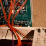
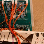
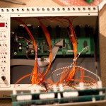
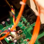
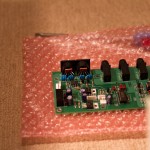
…. Well, as the photos below show, the transplant of the new IO board was a success, and I documented and photographed the internals during the process.
What a lovely device it is! Really well made. You can see also in the photos ( the last few especially ), the old board sitting outside the case, with the new board having been transplanted to it’s new home.
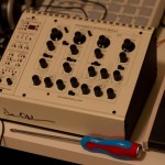
The last photo is the SEM now all fixed, and working perfectly, interfacing beautifully with all of my modern MIDI gear, posing with Tom’s screwdriver ( which I still have BTW, it’s a freaking awesome screwdriver! ).
So, I hope you all enjoyed that little experience, and soon, you’ll also be able to enjoy the sound of this newly fixed synthesis legend.
If you have any questions about this please feel free to ask.

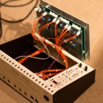

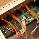
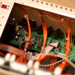



Frame the screwdriver!
MIDI isn’t based on voltage at all, but rather the current is specified as 5 mA. The 1990 spec shows 5 V supply voltages. However, I can see how using a lower voltage, such as 3.3 V for modern USB devices, could cause a problem.
Does anyone have a link to the original MIDI Specification (1984? 1988?) showing the 18 V circuits?
Hi Brian!
You are quite right, I just went back to check the MIDI spec and it is indeed based on a 5mA current loop, not any particular voltage. My apologies, I will update my article.
I think the reason I suspected voltage might be an issue is that the keyboard that I have gave out 18V from its MIDI out when I measured it, and successfully triggered the SEM. However, that’s not really relevant if it’s a current loop, since the voltage is not really important.
I’ll go back and have a look at the old board to see what the change was, but it could be that the opto-isolator (if there was one) was failing to trigger due to the diode forward voltage not being reached. However as most IR LEDs have a forward voltage of around 1.3V, this is also unlikely.
regards,
Luke